Sunday, December 25, 2011

Complete redesign of rear suspension

I purchased some software from Speed-Wiz that analyzes suspension as well as a thousand other cool things about my race car and discovered some good things and some bad things. The good thing is that my front roll center (the point in space where the front of the car rotates when leaning into a turn) is 3" off the ground. The bad news is that my rear roll center is 14" from the ground. It's common practice to have the rear roll center a little higher than the front roll center, but an 11" difference is silly. There was no way to correct this using the triangulated 4 link suspension I had and I would never be happy leaving it as it was, so I performed massive surgery on the rear suspension.  I decided to go with a 3 link suspension and use a Woblink for locating the suspension side to side. A 3 link has the benefit of having no bind through the range of suspension travel plus I can use all the bars and rod ends I already had. The Woblink is unusual but has proven effective on live axle cars in road racing and it provides a lower roll center than either a Panhard or Watts linkage can provide. There is a video at the bottom of the page showing it in action as well as a link to the Speed-Wiz website.
Here is the single top link with my newly fabricated front and rear brackets.

I decided to make new lower front brackets and move the holes farther forward, which adds length to the bars and reduces the amount that the axle moves in a forward and back direction while going through it's range of motion.

The new brackets, with the holes drilled in an arc that allows me to change bar location without having to change it's length

All three new suspension mounts welded into place.

This is the beginning of the Woblink. It is the bracket that hols the long link to the axle, and you can see it in the next picture, bolted to the axle flange.

The two brackets that hold the Woblink arms to the axle.

This is the Woblink pivot, also called a football. The top rod end attaches to the short bar going to the axle housing, the middle rod end goes to the long bar. I made the bottom pivot from thick wall tubing and added hardened steel bushings and a grease fitting. This pivot takes the side to side force of the rear suspension and becomes the roll center.

Here is the Woblink bolted to the diff.

I built the suuport that holds the Woblink in place out of 3/16" cold rolled steel plate. After this picture was taken, I removed considerably more material to take some weight out of it.

Here it is painted and installed on the car.

Note the bars bolted to the bottom of the support. They run forward under the diff and to the frame of the car, providing some stiffness to the support,

 Video of Woblink in action
Speed-Wiz website

Friday, December 9, 2011

EFI Problems sorted

Project update: anybody who has seen the car run knows it smokes pretty badly. The stock computer was not set-up to run the 24lb injectors I have and fuel was dumping into the cylinders. I got a custom tune using a product called Tweecer and the problem didn't go away. The Tweecer software shows real time readings of all engine sensors and my MAF sensor appeared to be faulty, so I bought a new one :(  The new one showed the same low voltage and a tech at Painless (wiring harness manufacturer) said I have a bad ground.

 I re-did all the ground connections, going as far as welding bolts to the frame that are used to attach the ground straps. Still no changes in the MAF readings so I put a voltmeter on it and lo and behold, the voltage was exactly what it's supposed to be. It turns out that I got a bad version of the Tweecer software and once that was corrected, the voltage displayed correctly. Still, the engine smoked. In the process of all these checks, I discovered that I had done my initial ignition advance based on the wrong marking on the timing tab and it was around 20 degrees too advanced. Corrected that and it ran 100% better but still smoked. I assumed that it was just a bunch of oil/gas coating the inside of the exhaust and would eventually burn off. Then I noticed that my air charge temperature reading was -20 C. I was not running the car outside so how could it be -20 C degrees? I replaced the ACT sensor and voila', the smoking seems to be going away and the car runs and sounds amazing. Here is the video of a drive around the kart track: Drive and walkaround

Tuesday, December 6, 2011

Battery Box

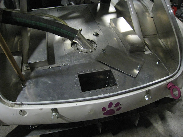
I had some doubts about my 9lb battery starting the V8 when hot so I installed a 15lb battery. I took this opportunity to move the battery as far back as possible to improve weight balance. I built an aluminum box into a cover under the rear hatch, bolted the battery in and finished it off with a nice cover held down by Dzus fasteners.

Tuesday, November 29, 2011

Ram air system

My original plan was to put a bellmouth in the headlight opening and ram air straight into the engine. However, the tires are too close to the opening and the top of the fender so there was no room for the pipe. Instead, I used the gap above the radiator and built a box to direct air to the engine.
This aluminum piece holds the hood pins but it's primary purpose is to block air from going over the radiator

Underneath the piece you can see a gap between the rad and the rad/fender support. I built a box that captures air going through this gap and direct it into the engine.

And here it is all finished. I do not have an air cleaner because I do not compete in a dusty environment, I don't follow other cars on a road course which can kick up dust and all air going into the engine has to pass through the mesh grille.

Wednesday, November 23, 2011

Updated diffuser and belly pan

The new floor is 3 inches lower than before so I had to lower the diffuser and the belly pan 3 inches as well. The belly pan fills the gap between the floor and the diffuser at the back and it goes beneath the differential.
On the old belly pan, I had to cut a hole in it for the differential to poke through but now I can use just a single piece of 20 gauge aluminum to do the job.

All that material above the yard stick has to be cut off the diffuser

The diffuser attaches to the belly pan then rises up towards the back.

The diffuser is held on at the back by adjustable struts. In this picture the diffuser is set at it's highest position

Monday, November 14, 2011

Rocker panels

When I lowered the floor 3 inches, I also lowered the side pipes so the bottom edge of the pipes was level with the bottom of the floor. This resulted in a 3 inch gap between the body and the side pipes where the rocker panels used to be. I made new ones out of 18 gauge aluminum and riveted them on.

Saturday, November 12, 2011

Video of car on track

I did a few laps on the kart track and have video from three different angles. The car smokes a lot but I think most of it is because the engine is running so rich. The handling is pretty good but understeers a little. I won't know the true handling until I get it outside on some real pavement. I think the engine sounds good.

Video from outside the car

Video from top of car

Video from side of car

Tuesday, November 1, 2011

Extra Transmission support

It turns out that my aluminum floor is not legal for the class because the rear tranny crossmember bolts to it and becomes load bearing, and aluminum is not allowed for load bearing structure. I simply added 1"x2" steel tube between the transmission crossmember and the frame rails and the problem is solved. The rest of the floor is held in with threaded aluminum rivets but for the crossmember, I welded 8mm nuts to the frame so it would be more secure.


Thursday, October 27, 2011

V8 radiator supports

The giant radiator I had for the V12 was so heavily modified that I decided to start fresh with a new, built for a 5.0, aluminum racing radiator. A mistake I made with the other one was that the uprights holding the rad also got in the way of shrouding the radiator. For this one I mounted it lower and farther back for improved weight distribution and I allowed lots of room for shrouding.

Here is the upper passenger side rad mount
Lower passenger side mount

And room behind the rad for dual shrouded fans.

Friday, October 21, 2011

More work on the floor and tranny mount

I put together the passenger side floor and finished up the rear of the drivers side floor. I am amazed how strong bent and riveted 1/8" aluminum is.


The floor is so strong that I am using it to support the transmission. Here you can see the steel mount I have bolted between the driver and passenger floor. To be safe, I am going to seem weld the entire floor and add some gussets.

I added a steel plate to add further strength and spread the load out a little bit. I will definitely have to keep an eye on the floor to make sure it's not buckling under the weight of the transmission.

Tuesday, October 11, 2011

The V8 is running

It has taken way too long to track down all the sensors, install and hook them up but I finally got it done. I also had to get oil lines made for the remote filter and weld oxygen sensor bungs into the exhaust. Here is the video of the first time I pushed the start button with the new engine. It runs a little rough because I didn't have the air charge temperature sensor plumbed into the intake system. After I took the video I just held the sensor in front of the MAF and it ran better. 
V8 first start up

Monday, October 3, 2011

New lowered drivers side floor

I started installing the new floor this week. It will be 4" lower, lighter and looks much better.
I ordered 1/8" aluminum sheet from a local supplier and had them bend the pieces for me.

And did a bunch of trimming and test fitting until the floor fit nicely. I used threaded rivets so I could bolt the floor to the frame and the transmission tunnel to the floor. At the back of the tunnel you can just see the modified driveshaft loop which now also serves as the rear mount for the tunnel.

I still have to add the vertical piece to fill in the rear of the floor, but you can see how I bolted it to the frame rail.

A test fit of the seat revealed that I will have to make an angled mount to attach the sliders, it shouldn't be that difficult.

Wednesday, September 14, 2011

Odds N Ends

I haven't stopped working on the car, I just haven't completed anything in a while. Here are a few things that have been started and are works in progress:
In this picture of the car in action, you can see how much airspace there is between the floor and the ground. This was a mistake on my part, I built the new floor higher than the original MGB floor and I decided to correct the mistake.

I cut out the whole floor, which was painful because so much work went into making it in the first place. The new floor will be lighter, lower and look better.

I also bolted the upper intake on and attached the wiring harness to some of the sensors/injectors.

And I am attempting to build fender flares out of aluminum. They should look pretty good when completed.

Wednesday, August 10, 2011

Fuel Lines

The V12 carbs used a low pressure fuel pump but the V8 uses a high pressure EFI pump. I removed the old pump and mounted this EFI pump behind the fuel cell. I would have liked to mount it lower but it would interfere with the diffuser.

And I mounted a new fuel filter along the frame rail. Notice the fancy clip-on connectors just like the factory uses. The filter is going to be around 5 inches from the exhaust pipe and I hope heat isn't going to be a problem. If it is, I'll construct a heat shield.

After the fuel filter, the lines (pressure and return line) run inside the frame rail and pop out just behind the battery.

And attach to the fuel rail and regulator.

Tuesday, August 2, 2011

Motor mounts and frame mod

With the 5.0, I had to flip the headers around in order to hook them up to the side pipes. This means that the frame had to be modified to clear the outlets on the headers.
Don't know why this pic uploaded sideways but here is the section on the drivers side that needed to be cut out.

And the new section is welded in, I still have to add a little front piece and weld the underside.

I debated what to do about motor mounts but finally decided to run 2" square tubing from the stock location on the block out to the frame rails. This is the passenger side.  I learned from the V12 that motor mounts sticking into the engine bay make it more difficult to remove the engine, so these ones bolt to the frame using grade 8 bolts..

 There is no cushion between the frame and the engine, they are solidly bolted at both ends