Wednesday, December 29, 2010

Sway Bar


According to my calculations, the MGB is going to be balanced towards understeer so I decided to install a sway bar on the rear of the car only. I found a sway bar calculator online and punched some numbers into it to figure out what I needed. Here is the calculator
I took some scrap pieces of aluminum, in this case some old kart motor mounts

Then I drilled a .750" hole in them to hold the sway bar in place

And sliced off the unneccesary metal and cut the blocks length wise to create a sway bar mount

Here is the passenger side mount bolted on

And the passenger side

This is looking in from the wheelwell

I cut and drilled some thick pieces of flatbar to act as arms and welded them on. The sway bar itself is hollow tube with a .750" OD and .500" ID

Here it is mounted but I still have to make the drop links that connect the bar to the suspension. Acccording to the sway bar calculator, the 6 holes will add from 69 lb/in to 163 lb/in to the suspension, and this should easily change the balance from undesteer to oversteer. Some in the Modified community say that mild steel works just fine as a sway bar as long as there isn't too much suspension travel, but I plan on taking the bar to get heat treated and turned into spring steel.

Saturday, December 25, 2010

Video of the engine running

When I first started it up
http://www.youtube.com/watch?v=fpdcSeUKbvQ

Up to temperature
http://www.youtube.com/watch?v=xmfOjZIM7yE

Thursday, December 23, 2010

Pictures of the engine bay

I have no recent pictures of the engine in the car so here are some taken today


Wednesday, December 22, 2010

Gauges

It was time to add gauges and I wanted to have easy access to the gauges and the switches.
I started with welding short bolts to the dash bar and fastened a piece of bent aluminum to it


I have enough room for 4 gauges but for now, I am running only 3. I used a hole saw to cut the holes then a die grinder to open them up slightly for the 2 5/8" gauges

In a race car, I think it makes sense to have the biggest gauges possible so they are easy to read at a glance. I am using Auto Meter 2 5/8" Oil Pressure, Oil Temperature and Water Temperature-all purchased from http://www.fasttoys.net/

I thought the open sides of the gauge box looked a little shoddy, so I added the side covers which also stiffens up the whole assembly

 I may add or change switches down the road and didn't want to have to build an all new gauge panel, that's why I added this lower panel instead of building it into the gauge box.

Tuesday, December 21, 2010

Exhaust

I bought mandrel bent mild steel tubes and collectors from Phil at http://www.fasttoys.net/ and spent 6 hours putting it all together today.
I got a bunch of 2" U-bends like this one and cut and welded them into an exhaust system

To speed things up, I took my regular old bandsaw and attached a couple of pieces of flat steel to either side of the blade, making a vertical bandsaw to cut the tubing

This is the start of the drivers side collector. The Jag V12 has four 3-into-1 exhaust manifolds so each side has two exhaust exits that need to be joined into one collector before going to the muffler.

Here is both drivers side tubes joined into one collector, before welding

And all welded up

And the passenger side, which was a lot easier to build

Another shot of the passenger side

And each side flows through a 2.5" Dynomax bullet muffler

Thursday, December 16, 2010

Master battery switch

I am required to have a master switch to kill all electrical and am given a choice between putting it on the back of the car or somewhere in the area of the A pillar so corner workers can turn if off if I flip the car. I wanted to have it close so I could also switch it off quickly so I put it just in front of the windshield on the drivers side. This would have meant running a cable from the passenger side battery to the switch then back to the starter on the passenger side, so I chose to move the battery to the drivers side and shorten the cables. I used #1 copper cable and ends from a local welding shop and soldered the ends on. I thought about using aluminum cable but there is little benefit because copper conducts electricity better and I could run a smaller copper cable than if I used aluminum.

Fuel system


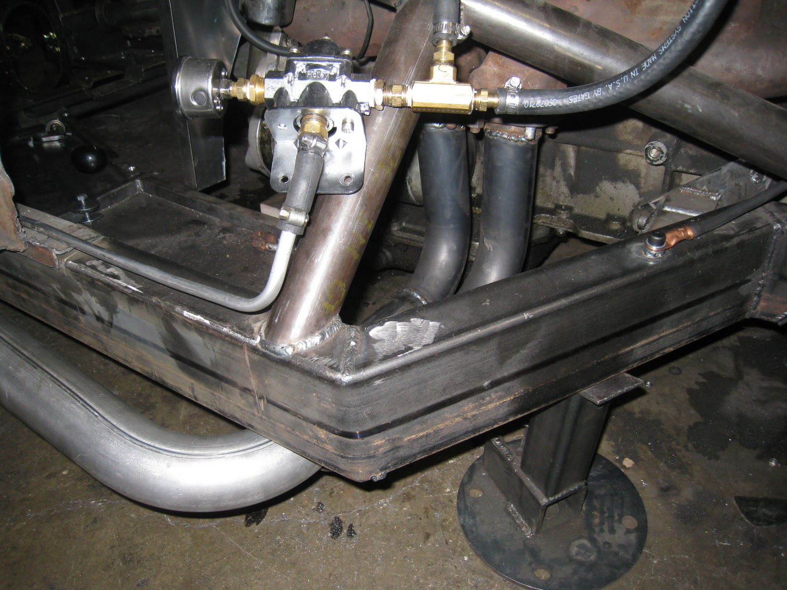
I read that it's important to mount an electric fuel pump as low and close to the fuel tank as possible in order to keep it primed with fuel at all times. My fuel cell is at the minimum ground clearance the rules allow so mounting the pump below that is impractical. As with everything else on the car, I am trying to keep everything accessible for easy repair, adjustment or replacement so I mounted the pump under an aluminum panel behind the fuel cell. Now I have to run a fuel line to the front of the car and after considering braided line and aluminum line, I decided to go with 3/8 i.d. aluminum line because it's the lightest and easy to work with. I'll add more pictures once the line is installed.

Tuesday, December 14, 2010

Wheel Frequency

Wheel frequency takes into account spring rate, motion ratio, sprung and  unsprung weight and is calculated in Hz. A higher number means stiffer suspension, lower means softer. I am only just learning about wheel frequency and wanted to know how my suspension will be before driving it. First thing I did was disconnect my shocks and set the car at normal ride height. I picked a spot close to where the middle of where the wheel would be mounted such as the  middle of the dust cap on the front spindle or centre of the axle flange on the back. Then I carefully measured the distance from the dust cap or flange to the ground and wrote that number down. Then I measured the distance from where the shock mounts on the rocker arm (such as the rear one in the above picture) to where the shock mounts on the chassis and wrote that number down. Using a floor jack, I raised the suspension up a set amount, in my case 10mm, then measured the amount the shock mount moved. I could move the suspension another 10mm and measure the amount the shock mount moved again and see if the motion ratio changed. In my case, when the wheel moves 10mm, the shock moves 7mm.  My motion ratio is 10 divided by 7=1.428. I used a bathroom scale to find out my front unsprung weight and Google to find out my rear unsprung weight(half the total weight of a Ford 9" plus the weight of one wheel and tire). I have also had my car on scales so I know my corner weights. Using this online calculator http://www.racingaspirations.com/?p=292 I plugged all the numbers in and found out that my wheel fequencies are 2.68Hz in the front and 2.53 Hz in the rear. From what I can tell, these are good numbers to start with on an EMod car. Since my car looks to be a little understeery, I will add a sway bar to the back of the car to balance it out. These numbers could change when the car is all ready to run because my corner weights could be higher than expected. Also, I can change the numbers just by changing the hole that the pushrod and/or shock are bolted to. With a little research, you can find out the numbers for your car and see what changing to lighter wheels or changing spring rates will do to the handling.

Friday, December 10, 2010

Axles

Axles are finally in. There's a bit of a story. I bought the differential housing on e-bay
and it was out of a 2000hp dragster. The axles were gun drilled 40 spine, which I
thought was overkill but since the price was good, I bought it. Once I had secured
the housing, I searched for a centre section and discovered that only spools are available
in 40 spline-oops! I ordered 31 spline axles from Moser and they just arrived.  I ordered them with
3 inch studs so I can use some thick spacers and still be safe. Notice how machined the rotors are,
every extra ounce has been taken off. The calipers are 4 piston aluminum jobs from Strange.

Thursday, December 9, 2010

Shifter moved

I noticed that I had to pull my hand back to reach the shifter
and thought that I could speed up my shifting if I only had to move
my hand sideways a little.

So I flipped the shift handle mount around, moving it ahead
several inches. Every little bit counts.

Belt tensioner

I need a tensioner for the belt that runs the water pump so I picked
up these pieces from Mid-Canada Bearing. The blue piece uses an
elastomer centre to allow the arm to move and put constant tension
on a belt or chain.


The hole in the middle of the pulley is too big so I took a brass
bushing, stuck it on a drill and spun it against a bench grinder-
poor man's lathe!

Here's the pulley with bushing

Installed on the car. There is some movement forward and back
of the tensioner so I may have to modify this later.

Wednesday, December 8, 2010

New front rotors

While changing calipers, I also changed rotors to a ventilated style.
The bottom one is the original unventilated rotor from a 1967 Jaguar XJ6 and the top one is
from a 1968 XJ6. I had .150" machined off off to take some weight off. The brake shop
advised against taking off so much material because they might warp but I assured
them that this was a racing application and long term life wasn't a big consideration. If
I find that braking performance is stellar and I want to lose even more weight, I can remove a
spacer from the Wilwood calipers and run the lighter unventilated rotor.

Losing unsprung weight

This thick metal spacer is on the front suspension and used to
attach a sway bar on a Jaguar

On the left is the removed bracket, which is quite heavy, and
on the right are the two spacers used to replace it

Here they are installed. I don't know how much weight I took off
but I estimate 1-2 lbs per side. I'll get a scale on it later.

Monday, December 6, 2010

Wilwood brakes

Stock Jag 3 piston front caliper is 11lbs 14oz

Wilwood 4 piston caliper is 4lb 2oz

Mounted with the new ventilated disc

Driveshaft from Denny's Driveshaft service
 http://www.dennysdriveshaft.com/
fit perfectly

New Jaz fuel cell filler has a one-way flap to
keep fuel in the cell in case of a rollover

Short driveshaft

Really small driveshaft or really big caliper?

Bracing front pivot mount

I noticed that this bracket on the front suspension would
flex when somebody jumped up and down on the car

So I added this bracket that attaches it to the shock crossmember.
It's under tension so the metal didn't have to be thick.

Rear shelf

In order to fit the hose from the fuel filler to the cell, I had
to split the rear shelf into three pieces and add a curved piece of
pipe to get around the rollcage. Adjusting the shocks is
easier because each side just lifts up to reveal the shock.

Amazing luck with aluminum

I couldn't figure out how to make the complex curved piece
that goes from the tranny tunnel to the firewall, but then I remembered
that I saved the aluminum housings from the sodium lights that
were replaced in our building. I took a light housing

Cut out the piece I needed

And it fit perfectly!!